Custom ToolBlock Generic Finder
Custom ToolBlock Generic Finder is a finder that allows user to find a generic feature using custom tool block. A generic features is a System.Object which can be of any .NET type. It provides the user the flexibility to locate any type of feature such as lines, angles, fiducials etc. Here is an example to show how to set a point and a line segment as one generic feature in custom toolblock.
Add
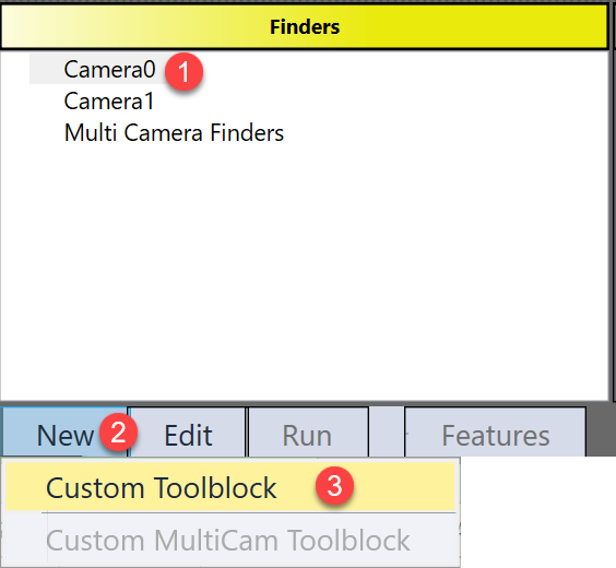
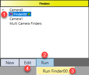
Custom Toolblock Line Finder is available in Generic Features Finder HMI control. The steps to add it are:
-
Select one image
-
Click "New" button under the Finders panel
-
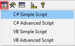
Choose "Custom Toolblock", then a custom toolblock generic finder will be available for user to edit.
Setting
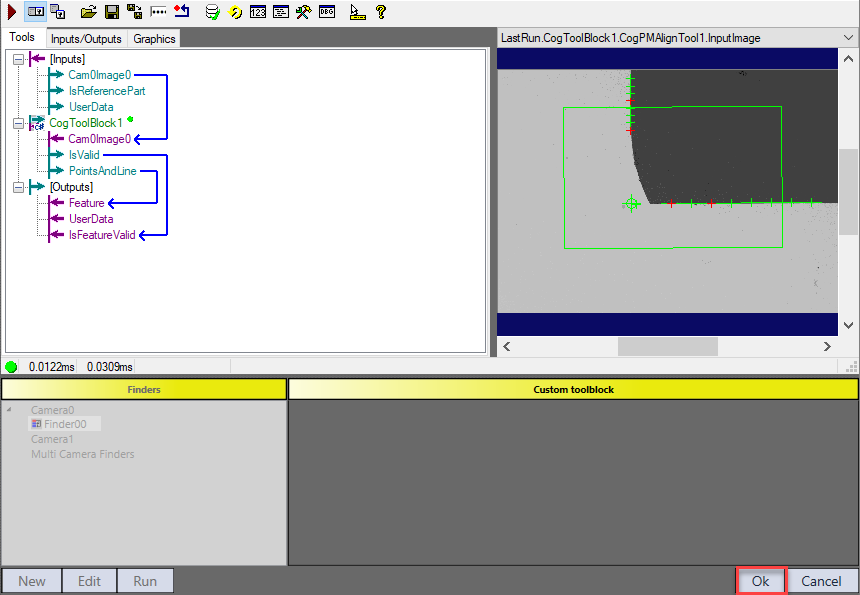
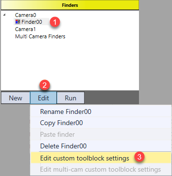
Settings of this finder are all contained in its custom toolblock. Follow the steps to open the toolblock: 1) select the finder, 2) click “Edit” button, 3) choose “Edit custom toolblock settings”.
However, the input image of this toolblock is initially null because the finder has not been run yet.
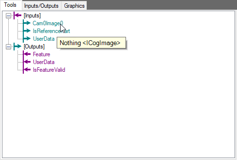
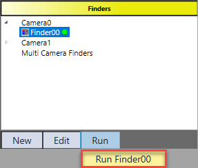
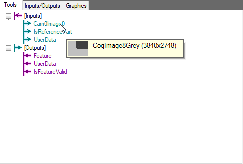
To get input image, click “Ok” button, run the current finder once in Finder panel, and open the toolblock again. Then, the toolblock is ready for user to customize.
Inputs
| Parameters | Type | Description |
|---|---|---|
|
Cam0Image0 /Cam1Image1 |
Cognex.VisionPro.ICogImage | Input image(s) from corresponding camera(s) |
| InReferecePart | Boolean | A input pin for user to decide whether and how to use it for golden pose training using reference part |
| User Data | Cognex.VisionPro.CogDictionary |
Contains a CogDictionary with user specified data. |
Outputs
|
Parameters |
Type |
Description |
|---|---|---|
|
Feature |
Object |
The result generic feature. |
|
IsLocationValid |
Boolean |
The flag to show whether a feature is found or not. Later will be used to decide whether or not to use this feature to compute pose. |
|
UserData |
CogDictionary |
More data can be stored inside UserData as an output, this UserData is only accessible in scripting. |
Editing
Custom Tool Block Generic Finder does nothing unless user configure vision tasks inside it. Users can directly add tools here or add an inner tool block and edit tools within it. The latter is recommended as it will keep finder neat.
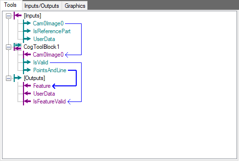
1. Within the internal tool block, add inputs and outputs
To contain a corner point and a line segment into one generic feature, user can use CogDictionary as the output type.
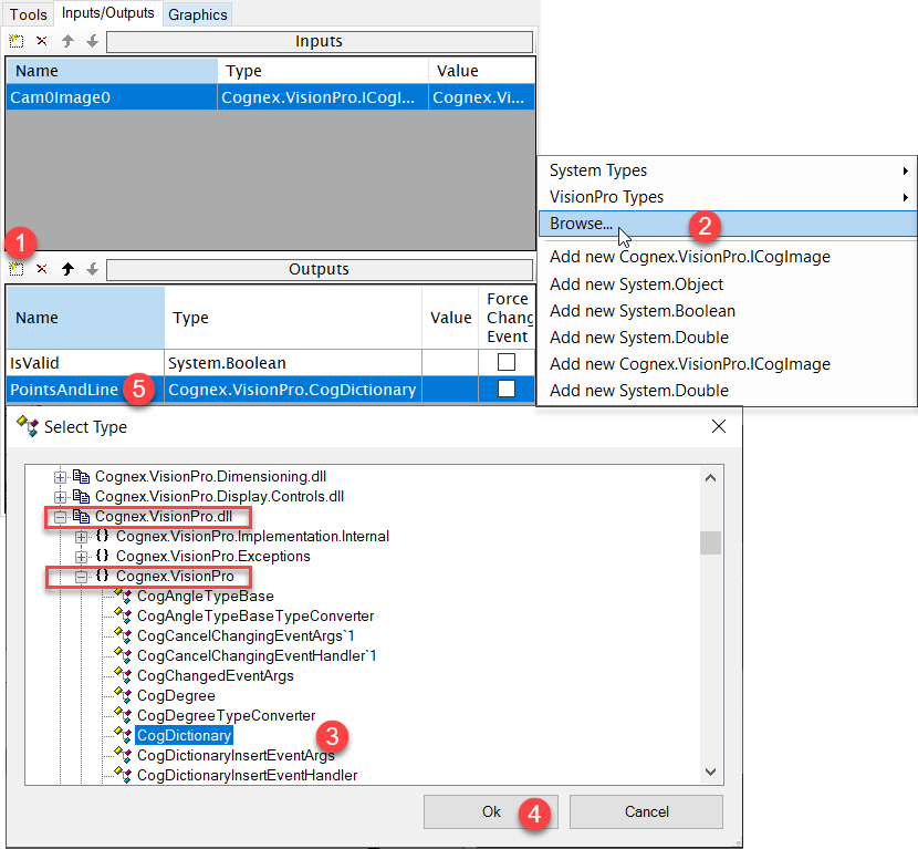
Add another output pin "IsValid" as a Boolean.
2. Link inner and out tool block input and output pins
3. Editing inner tool block
User have the flexibility to design how the target line and point should be found, how the output generic feature should be composed in this toolblock. Here is an example for reference:
1) Add CogPMAlignTool tool to locate the part.
The PatMax tool here helps locate the part and guide the following CogCornerFindTool to target specific ROI on part in run time.
2) Add CogFixtureTool to create a fixture space.
CogFixtureTool creates a new fixture space based on part's current pose.
3) Add CogFindCornerTool to find two lines and one corner point.
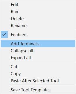
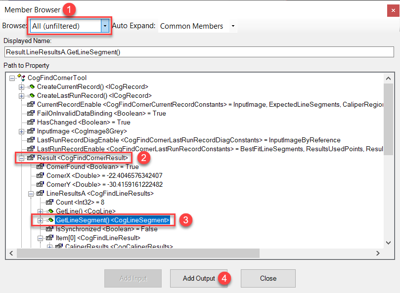
CogFindCornerTool outputs only the corner point by default. To add an extra line segment output, right click the CogFindCornerTool and select "add terminal", in the opened dialog select the target line segment and then click "Add Output".
Link CogCornerFinderTool's input image to the source image (whose selected space is Home2D) of this toolblock, and change CogCornerFinderTool's ROI regions to use the fixture space generated by the CogFixtureTool. This will make sure CogCornerFinderTool track the run time part and output results in Home2D.
I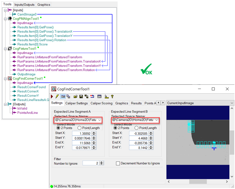
4. Add Scripting inside inner tool block to contain the point and the line segment into a CogDictionary output and check whether tool block runs successfully
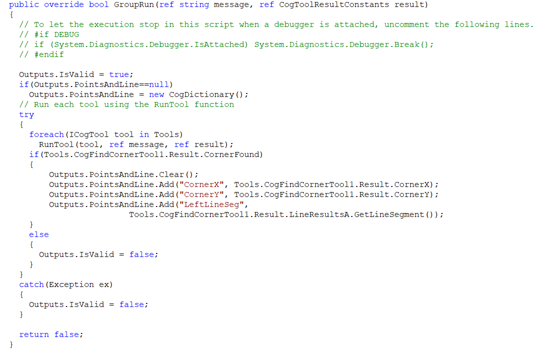
5. Test inside inner tool block to see if "IsValid" output reflects the ok/ng result correctly.
Run
After setting up the tool block, click "Ok" button and run the finder to see result.